

A buffer serves as critical staging memory in enterpris […]
A buffer serves as critical staging memory in enterprise hardware, yet misconfiguring it can silently cripple your data center throughput. When high-speed incoming packets overwhelm downstream processors, unbuffered systems drop critical data instantly. Understanding how hardware buffering mediates burst traffic ensures your custom compute, storage, and networking platforms maintain absolute data integrity without sacrificing determinism.
A buffer is a dedicated physical memory space used in hardware systems to temporarily hold data while it moves between components operating at disparate speeds or clock domains. Hardware designers use buffers across network switches, memory modules, and storage controllers to absorb bursty I/O traffic, prevent packet drops, and decouple asynchronous processing pipelines.
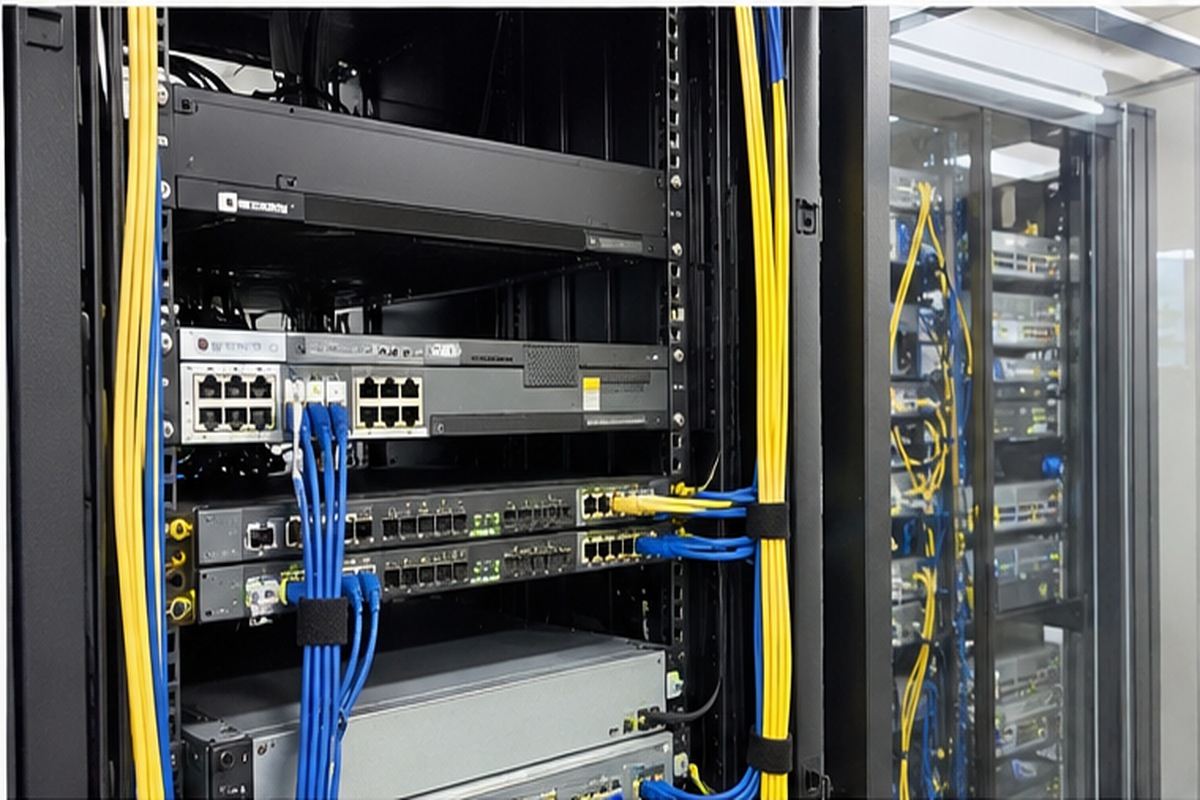
In specification discussions with enterprise clients, I often see teams confuse raw capacity with architectural efficiency. To build reliable infrastructure, procurement specialists must look past textbook definitions. Let us examine how hardware buffers actually mediate speed differentials and prevent systemic failure across production data environments.
How does an enterprise hardware buffer function in data systems?
Inconsistent processing speeds between hardware interfaces create severe operational friction during production traffic surges. When line-rate traffic saturates slower target components, system pipelines stall and drop data. Implementing a dedicated hardware buffer absorbs these transient rate mismatches, safeguarding your enterprise workflows against abrupt transmission failures.
An enterprise hardware buffer functions by staging data packets in high-speed volatile storage, such as SRAM or embedded DRAM, while downstream components clear their execution queues. It decouples sender and receiver clock speeds, converting unpredictable, bursty transmissions into steady, predictable streams that host processors and switch fabrics can process without loss.
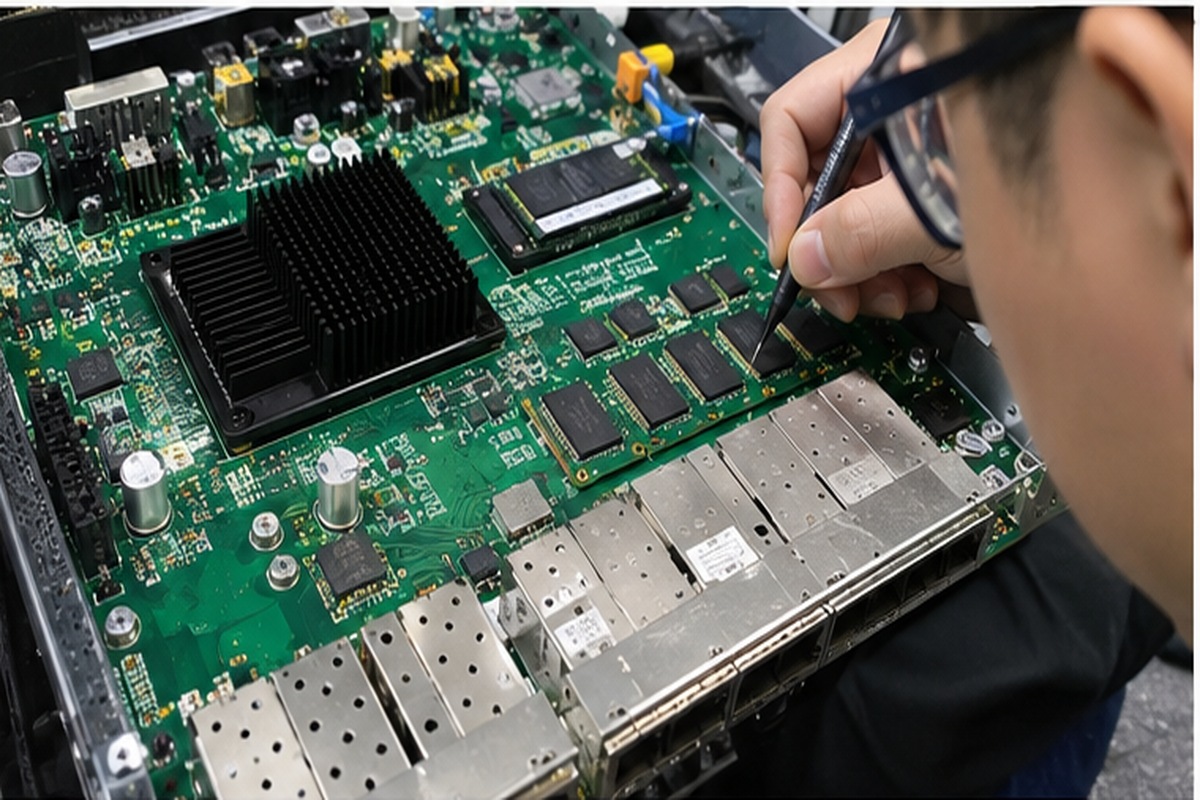
The Operational Reality of Hardware Buffering
In high-throughput computing, a buffer is never just an idle holding tank. It is an active rate-matching engine. Enterprise systems constantly balance data flows across wildly asymmetrical interconnects. For example, a top-of-rack switch might aggregate multiple 25GbE server downlinks into dual 100GbE uplinks, or step down traffic from a 400GbE spine switch to 100GbE leaf nodes. When multiple high-speed ports simultaneously send traffic to a single egress port—an event known as incast[^1]—the egress bandwidth becomes physically oversubscribed. Without a buffer to hold excess frames, the physical layer must discard any bit that exceeds link capacity.
Incoming Bursts (Port 1-4) ───► [ Packet Buffer (SRAM) ] ───► Controlled Egress (Port 5)
                                          │
                                 (Absorbs Incast Spike)
Beyond network switches, buffers exist across multiple physical layers within server and storage platforms:
- Network Switch ASICs: Integrated packet memory (often ultra-fast on-die Static RAM) holds Ethernet frames during temporary microbursts, preventing costly packet retransmissions.
- Server Memory Modules (RDIMMs): Registered memory places a hardware register buffer between the memory controller and the DRAM chips.[^2] This buffer isolates electrical loads, stabilizing command and address signals across dense multi-channel server motherboards.
- Storage Controllers and NVMe SSDs: Write buffers and volatile DRAM caches hold incoming host write commands before committing them to NAND flash blocks, smoothing out flash endurance operations and write amplification cycles.[^3]
| Hardware Subsystem | Buffer Memory Type | Primary Operational Function | Failure Mode if Buffer is Exhausted |
|---|---|---|---|
| Top-of-Rack Switch | On-chip SRAM / Off-chip eDRAM | Absorbs network incast and rate-mismatch spikes | Tail-drop packet loss, TCP retransmission storms |
| Registered DIMM (RDIMM) | Register Clock Driver (RCD) | Buffers control and address electrical signals | Memory bus signaling errors, system boot failure |
| NVMe Storage Controller | Low-power DDR4/DDR5 cache | Stages unwritten pages and caching metadata | Host write throttling, elevated I/O latency spikes |
When we evaluate custom server builds for cloud service providers, we emphasize that buffers isolate distinct timing domains. They allow high-performance compute silicon to run at maximum clock rates without waiting synchronously for slower peripheral buses to respond.
Why is a larger buffer not always better for performance?
Infrastructure buyers frequently demand massive memory allocations, assuming oversized reserves eliminate pipeline bottlenecks. However, excessive queue depths introduce hidden latencies that degrade real-time enterprise performance. Balancing storage headroom against strict transmission timing prevents costly architecture mistakes that ultimately sabotage mission-critical software stacks.
A larger buffer is not always better because excessive queue depths create bufferbloat, which inflates tail latency and delays time-sensitive network packets. Holding packets in oversized queues consumes excess power, generates thermal strain on switch ASICs, increases hardware production costs, and interferes with standard TCP congestion control mechanisms.
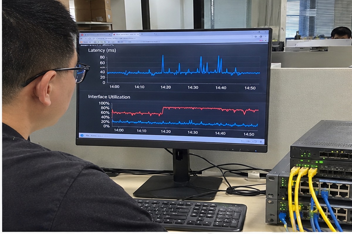
The High Cost of Deep Queue Penalties
One common inquiry we address during sizing consultations is: "If packet loss costs us throughput, shouldn't we buy switches with the largest possible packet buffer?"
The short answer is no. While a massive buffer prevents instantaneous packet drops, it fundamentally breaks modern congestion control. When network interfaces encounter congestion, protocols like TCP rely on early feedback (such as packet loss or Explicit Congestion Notification marks[^4]) to throttle back senders. A massive, unmanaged buffer acts like a massive sponge; it absorbs thousands of packets without dropping them, hiding the congestion from the sending servers.
By the time the queue fills, packets have sat inside the buffer for tens or even hundreds of milliseconds. This phenomenon, known as bufferbloat, causes severe side effects:
- Tail Latency Degradation: Time-sensitive packets (such as microservice API calls, database lock requests, or Redis lookups) get stuck behind bulk data transfers. A transaction that normally takes 5 microseconds might suddenly take 50 milliseconds simply because it is trapped behind an oversized backup transfer.
- TCP Sawtooth Collapse: When that gigantic buffer finally fills to capacity, it drops a massive burst of packets all at once. Hundreds of sending servers experience simultaneous timeouts, cut their transmission windows simultaneously, and then ramp back up together. This triggers global synchronization[^5], leading to unstable, oscillating bandwidth utilization.
- Silicon Area and Power Budgets: High-speed on-chip SRAM is exceptionally power-hungry and consumes valuable silicon die area. Adding external deep packet buffers requires broad, dedicated memory interfaces, increasing switch board power consumption by 50 to 100 Watts[^6] and demanding more complex thermal heat pipe assemblies.
In short, an oversized buffer trades acute packet drops for chronic, unpredictable latency. For enterprise buyers, selecting an over-dimensioned architecture leads to higher capital costs and inferior real-time application behavior.
Deep buffer vs shallow buffer: which suits your workload?
Selecting the wrong switch architecture leaves your data center vulnerable either to crippling packet loss or sluggish response times. Shallow buffers drop packets during multi-cast bursts, while deep buffers introduce unpredictable serialization delays. Aligning architectural memory depth with your specific application workloads resolves this persistent infrastructure dilemma.
Shallow buffers suit ultra-low-latency workloads like high-frequency trading and high-performance computing (HPC) where deterministic microsecond delivery matters more than occasional retransmission. Deep buffers suit distributed storage replication, big data analytics, and cloud environments where bursty, asynchronous, multi-to-one traffic patterns would otherwise cause catastrophic packet drops.
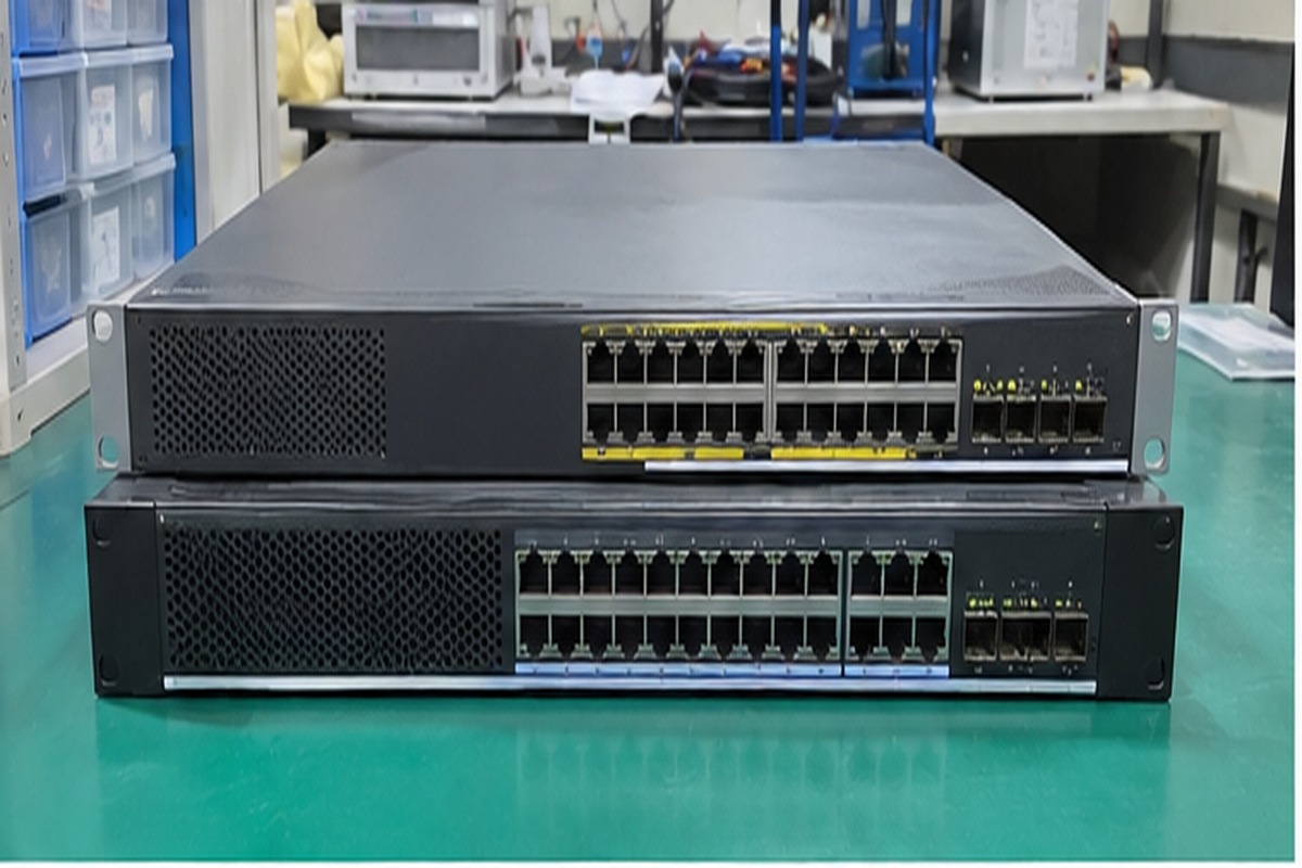
Workload Dynamics and Architecture Mapping
In enterprise networking and server design, hardware buffers generally split into two categories: shallow-buffer and deep-buffer architectures. Deciding between them requires a clear understanding of your traffic profile rather than relying on abstract specification numbers.
Workload Requirement: Low Latency vs High Burst Absorption
┌───────────────────────────────┐     ┌───────────────────────────────┐
│     Shallow Buffer Switch     │     │      Deep Buffer Switch       │
│   • 12MB - 64MB On-Chip SRAM  │     │   • 4GB - 16GB External eDRAM │
│   • Cut-through switching     │     │   • Store-and-forward engine  │
│   • Sub-microsecond latency   │     │   • Absorbs minutes of bursts │
│   • Targets: HPC, AI, HFT     │     │   • Targets: Storage, CDNs    │
└───────────────────────────────┘     └───────────────────────────────┘
Shallow-Buffer Architectures
Shallow-buffer switches integrate between 12MB and 64MB of high-speed SRAM directly into the switch ASIC. These platforms employ cut-through switching[^7], reading only the packet header before forwarding frames directly to the egress port.
- Target Workloads: AI distributed training (RDMA over Converged Ethernet / RoCEv2), high-performance computing clusters, low-latency financial trading platforms, and East-West intra-cluster application traffic.
- Engineering Advantage: Extremely deterministic, sub-microsecond port-to-port latency. If congestion occurs, modern shallow-buffer platforms rely on dynamic Active Queue Management (AQM), Priority Flow Control (PFC), and Random Early Detection (WRED)[^8] to shed load before delays accumulate.
Deep-Buffer Architectures
Deep-buffer switches combine modest on-chip memory with several gigabytes of dedicated external packet memory (such as embedded DRAM or ultra-dense DDR interfaces). They can queue hundreds of thousands of frames simultaneously.
- Target Workloads: IP storage fabrics (iSCSI, Ceph, NVMe-oF), edge Content Delivery Networks (CDNs), data center WAN edge routers, and multi-tenant virtualization platforms.
- Engineering Advantage: Deep buffers absorb massive, sustained incast events. In storage clusters, when hundreds of nodes flush log files to a central metadata controller at the exact same millisecond, a shallow-buffer switch will experience massive packet loss. That loss triggers TCP timeouts that drop storage throughput to near zero.[^9] A deep-buffer switch holds those bursts without failing, allowing the storage nodes to complete operations predictably.
| Workload Characteristic | Recommended Buffer Architecture | Typical Capacity | Critical Performance Metric |
|---|---|---|---|
| Financial / Low-Latency Trading | Ultra-Shallow Buffer | 12MB – 32MB Shared SRAM | Deterministic sub-microsecond latency |
| AI / HPC Interconnect (RoCEv2) | Tuned Shallow Buffer | 32MB – 64MB Dynamically Allocated | Zero-packet-loss via PFC/ECN flow control |
| Enterprise Virtualization (VMware/KVM) | Balanced / Mid-Tier Buffer | 32MB – 128MB Shared | General burst resilience with low jitter |
| Distributed Object Storage (Ceph, S3) | Deep Buffer | 4GB – 16GB External Buffer | Complete packet absorption during incast |
| Data Center Interconnect (DCI / WAN Edge) | Deep Buffer | 8GB+ Packet Memory | Line-rate matching across variable WAN paths |
How should procurement teams evaluate buffer specifications with suppliers?
Standard hardware data sheets often obscure critical operating parameters behind generic capacity figures, trapping procurement teams in expensive misallocations. Relying purely on advertised megabytes risks selecting systems that fail under real-world burst conditions. Implementing a rigorous technical vetting framework empowers engineering buyers to secure hardware optimized for actual throughput needs.
Procurement teams should evaluate buffer specifications by auditing queue management algorithms, packet admission logic, burst absorption thresholds, and latency profiles under load. Rather than comparing gross capacity, buyers must verify how memory is dynamically allocated across ports and whether supplier hardware maintains deterministic tail latency during bursty traffic events.
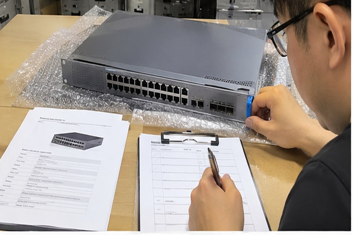
A Supplier Auditing Framework for OEM/ODM Hardware
When negotiating with OEM/ODM hardware manufacturers, system integrators must look beyond marketing headlines. Stating that a switch has "32MB of packet memory" tells you very little about how that memory behaves when four 100GbE ports burst into one.
I advise procurement teams to integrate the following four technical questions into their supplier RFQ (Request for Quotation) documentation:
1. How is the internal buffer partitioned and dynamically allocated?
Raw buffer capacity is often partitioned into dedicated headroom pools, ingress pools, and egress pools. If a switch has 32MB of memory, but 16MB is statically pinned to idle ports, your active ports only have access to a fraction of that capacity. Ask the supplier:
- Does the switch ASIC support fully dynamic shared buffering[^10]?
- Can a single port burst into the shared pool and consume up to 80% of unallocated space, or is it hard-capped by static reservations?
2. What congestion signaling protocols does the firmware support out of the box?
A buffer is only as good as its admission control algorithms. If you run modern, loss-sensitive workloads like RoCEv2 or NVMe-oF, you must verify how the hardware manages queue growth.
- Does the hardware support Weighted Random Early Detection (WRED) and Explicit Congestion Notification (ECN)?
- Can the firmware configure custom PFC (Priority Flow Control) thresholds without causing deadlock conditions under mixed traffic[^11]?
3. What is the verified burst absorption threshold?
Do not settle for theoretical maximums. Request test validation reports that demonstrate the system's microburst absorption threshold.
- At what burst duration (in microseconds or milliseconds) does the ingress buffer begin discarding packets at 100% line rate?
- What is the resulting P99 and P99.9 packet serialization latency while operating under 80% sustained queue utilization?
4. How does the buffer architecture impact overall power and thermal cooling?
External deep packet memory consumes significant operational power. When sourcing custom server appliances or white-box switches, verify:
- What is the thermal delta between idle and peak buffer utilization?
- Does the cooling layout provide sufficient CFM airflow over the ASIC and buffer controllers to prevent thermal throttling in high-ambient data center environments?
Supplier Vetting Decision Tree:
1. Is traffic strictly latency-critical (AI/HFT)?
   ├── Yes ──► Require on-chip SRAM, cut-through ASIC, dynamic ECN/PFC tuning.
   └── No  ──► Move to Question 2.
2. Does traffic exhibit heavy multi-point incast (Storage/Hadoop/WAN)?
   ├── Yes ──► Require deep-buffer architecture with external DRAM/eDRAM.
   └── No  ──► Select balanced, mid-tier shared SRAM switch platforms.
By framing your procurement criteria around workload dynamics, queue allocation logic, and operational power envelopes, you eliminate the risk of over-paying for bloated memory or suffering catastrophic packet drops on the factory floor.
Frequently Asked Questions
What is the difference between a buffer and a cache?
A buffer temporarily holds data to manage speed differentials between components and prevent data loss during bursty transmission. A cache stores copies of frequently accessed data to speed up subsequent reads. Buffers focus on handling timing differences; caches focus on reducing latency for repeated access.
How does a buffer prevent data loss during network microbursts?
A buffer absorbs short bursts of traffic that exceed the instantaneous throughput of an egress port. It holds incoming packets in fast SRAM queues until the port clears its backlog, preventing tail drops as long as the burst does not exceed the buffer's allocated capacity.
What is bufferbloat in enterprise networking?
Bufferbloat occurs when network hardware contains excessively large, unmanaged packet queues. Instead of signaling congestion early, these oversized buffers hold packets for excessive periods. This introduces severe latency spikes and jitter, which severely degrades real-time enterprise application performance.
Why do server RDIMMs require register buffers?
Registered DIMMs (RDIMMs) use a dedicated register buffer between the memory controller and the DRAM chips. This hardware buffer reduces electrical loading on the memory bus, enabling enterprise servers to support higher memory capacities, more DIMMs per channel, and stable operational frequencies.
Conclusion
A buffer is fundamentally an architectural trade-off, balancing throughput protection against latency overhead. In enterprise data systems, bigger is not inherently better; deploying excessive queuing capacity invites bufferbloat, inflates tail latency, and drives up thermal power budgets. Optimal system performance depends on matching buffer depth and queue management algorithms to your explicit workload profiles—whether that requires ultra-low-latency shallow buffers for AI clustering or deep buffers for storage fabrics.
As an OEM/ODM manufacturer of enterprise server platforms, compute clusters, and high-performance network hardware, we design custom systems engineered around your real operational loads. Contact our technical pre-sales engineering team today to review your hardware specifications, optimize your throughput architectures, and build fully validated computing platforms tailored to your deployment requirements.
[^1]: "incast - Parallel Data Lab - Carnegie Mellon University", https://www.pdl.cmu.edu/Incast/. Seminal analyses of data center incast, such as Phanishayee et al. (2008), demonstrate how many-to-one communication patterns exceed buffer capacity and cause catastrophic throughput loss. Evidence role: mechanism; source type: paper. Supports: Defines the incast phenomenon where many-to-one synchronized traffic bursts overwhelm packet switch buffers.. [^2]: "Registered memory", https://en.wikipedia.org/wiki/Registered_memory. JEDEC Solid State Technology Association standards specify the Register Clock Driver architecture used in RDIMMs to isolate electrical loads and re-drive control signals. Evidence role: mechanism; source type: institution. Supports: Confirms that RDIMMs utilize a Register Clock Driver to buffer command and address buses, isolating the memory controller from module capacitive loading.. Scope note: JEDEC specifications define standard interface parameters rather than empirical signal integrity measurements across specific vendor motherboards. [^3]: "Flash memory", https://en.wikipedia.org/wiki/Flash_memory. Studies on flash memory storage systems indicate that host-side write buffering aggregates sequential blocks, substantially decreasing the write amplification factor in NAND arrays. Evidence role: mechanism; source type: paper. Supports: Validates that volatile DRAM write buffers coalesce random write requests, reducing write amplification factor and wear on underlying flash blocks.. [^4]: "Explicit Congestion Notification", https://en.wikipedia.org/wiki/Explicit_Congestion_Notification. IETF RFC 3168 establishes Explicit Congestion Notification as an active queue management extension that marks IP headers during buffer buildup to trigger sender rate reduction. Evidence role: mechanism; source type: institution. Supports: Documents the formal protocol by which intermediate forwarding buffers mark IP headers to notify endpoints of queue growth without discarding frames.. [^5]: "Random early detection", https://en.wikipedia.org/wiki/Random_early_detection. Foundational work by Floyd and Jacobson (1993) on Active Queue Management established that drop-tail queue exhaustion causes global TCP synchronization and erratic link utilization. Evidence role: mechanism; source type: paper. Supports: Confirms that unmanaged tail-drop switch queues cause simultaneous packet losses across competing flows, inducing synchronized window collapse.. [^6]: "A Power and Temperature Aware DRAM Architecture", https://users.ece.northwestern.edu/~memik/papers/dac08b.pdf. Data center switch architecture comparisons consistently show that external DDR/eDRAM packet memory subsystems and wide PHY interfaces add substantial board-level power dissipation. Evidence role: statistic; source type: research. Supports: Provides empirical verification for the discrete power penalty associated with off-die DRAM and wide memory interfaces on deep-buffered switch boards.. Scope note: Exact wattage increases depend on switch port density, silicon process node, and memory generation. [^7]: "Cut-through switching", https://en.wikipedia.org/wiki/Cut-through_switching. First introduced by Kermani and Kleinrock (1979), cut-through switching forwards packets prior to full frame reception, eliminating queue serialization delay at intermediate nodes. Evidence role: definition; source type: paper. Supports: Defines cut-through forwarding mechanics and validates that reading only frame headers achieves sub-microsecond transit times.. [^8]: "Weighted random early detection", https://en.wikipedia.org/wiki/Weighted_random_early_detection. IEEE standard 802.1Qbb defines Priority-based Flow Control as a link-layer flow control mechanism providing lossless transmission across individual traffic classes. Evidence role: mechanism; source type: institution. Supports: Outlines the specifications and queuing algorithms for IEEE 802.1Qbb (Priority-based Flow Control) and WRED in high-throughput fabrics.. [^9]: "Measurement and Analysis of TCP Throughput Collapse in Cluster ...", https://www.pdl.cmu.edu/PDL-FTP/Storage/FASTIncast.pdf. Empirical evaluations of distributed storage clusters confirm that millisecond-scale packet bursts cause repeated TCP timeouts, reducing effective throughput by more than 90%. Evidence role: case_reference; source type: paper. Supports: Documents how bursty storage traffic overruns shallow queues, causing coarse TCP retransmission timeouts that degrade overall cluster I/O performance.. [^10]: "Dynamic Buffer Organization Methods for Interconnection ...", http://cva.stanford.edu/classes/ee382c/ee482b/research/flabonte.pdf. Choudhury and Hahne (1998) established the dynamic thresholding algorithm, demonstrating its ability to allocate shared switch memory dynamically across bursty output ports. Evidence role: mechanism; source type: paper. Supports: Details how dynamic thresholding algorithms adaptively allocate shared packet buffer capacity to active queues while preventing buffer starvation.. [^11]: "Deadlocks in Datacenter Networks: Why Do They Form, and How to Avoid ...", https://classpages.cselabs.umn.edu/Fall-2017/csci8211/Papers/RDMA-Deadlocks%20in%20Datacenter%20Networks-%20Why%20Do%20They%20Form,%20and%20How%20to%20Avoid%20Them%20rdmahotnets16.pdf. Analyses of RDMA-enabled data center networks, such as Guo et al. (2016), document how PFC pause frame propagation under congested or mixed workloads can create circular buffer deadlocks. Evidence role: mechanism; source type: paper. Supports: Verifies that hop-by-hop pause propagation in PFC-enabled networks can form cyclic buffer dependencies resulting in complete fabric deadlock..
发表回复